Summary
- LR and LC circuits
- AC voltages
- Phasors
Bonus question Ch. 31
- Written Quiz Ch.31

- Simple Circuits
- Interactive circuit applet (Falstad)
- Interactive circuit applet (Fendt)
- Purely resistive, animated applet
Example #1
- Purely capacitive, animated applet
- Current leads the voltage in a capacitor
(capacitor acts like wire when voltage first applied)
- Capacitive reactance
Example #2
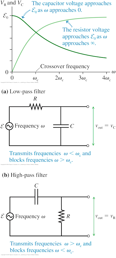
- RC filters
- Purely inductive, animated applet
- Current lags the voltage in an inductor
(inductor acts like open circuit when voltage first applied)
Example #3
- The series RLC circuit animated applet
- impedance
- resistive phasors
- resonance
PSE10 QQ.31.02
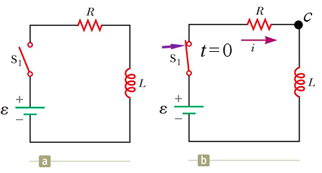
Consider the circuit shown below, letting V = 0 at the negative terminal of the battery. Switch S1 is closed at time t = 0. At that instant, the electric potential at point c is _____.
A. zero
B. ½ℰ
C. ℰ
D. (Lℰ) ⁄R
Answer
pse9 33.3
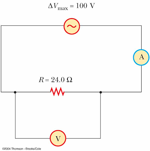
What do the voltmeter and ammeter read in the figure?
A. 100 V, 4.17 A
B. 100 V, 240 mA
C. 70.7 V, 2.95 A
D. 70.7 V, 1.70 A
Answer
pse9 33.21
What is the maximum current when a ε0 = 48 V generator
at 90 Hz is connected across a 3.70 µF capacitor?
A. 100 mA
B. 75.0 mA
C. 48.0 mA
D. 16.0 mA
Answer
pse9 33.11
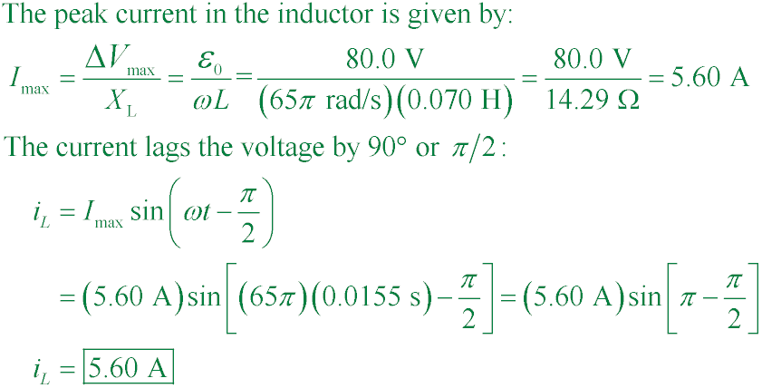
What is iL at t = 15.5 ms in the figure if ΔVmax = 80.0 V,
ω = 65.0π rad/s, and L = 70.0 mH?

A. 14.5 mA
B. 132 mA
C. 825 mA
D. 5.60 A
Answer
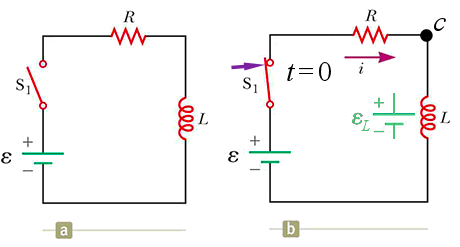
C. ℰ
No current flows at first because the back emf of the inductor matches the emf of the battery, leaving no potential difference across the resistor to drive current through it. As the back emf dwindles, however, current begins to flow and eventually reach its maximum value when the back emf is zero and the inductor acts like a wire.
C. 70.7 V, 2.95 A

A. 100 mA

D. 5.60 A
